logo
Supal (Changzhou) Precision Tools Co.,Ltd
About Us
Your Professional & Reliable Partner.
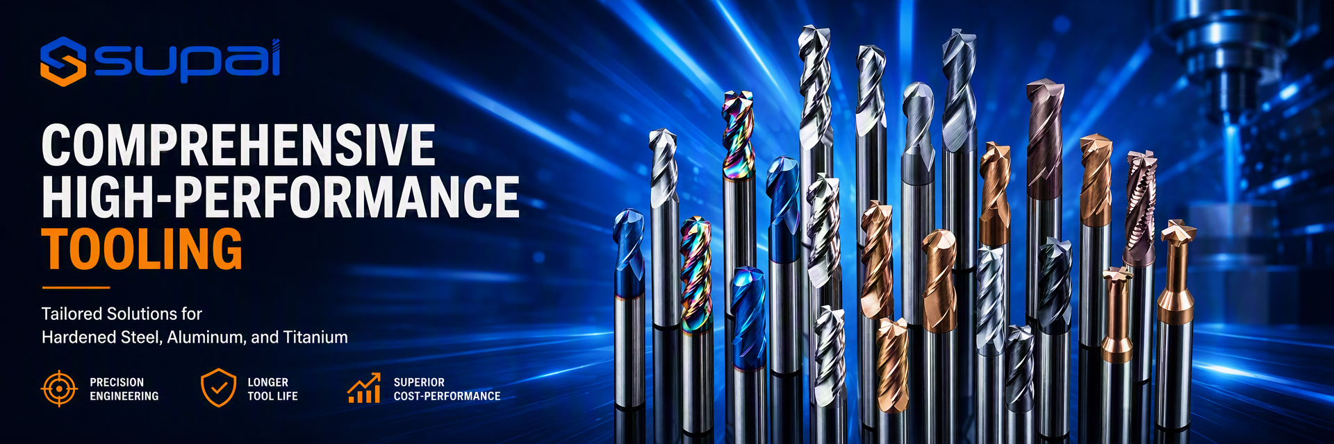
Supal (Changzhou) Precision Tools Co., Ltd. has been engaged in design, production and marketing of solid carbide tools for many years,with total investment of more than 10 million, and consists of a group of experienced employees..As a professional tools manufacturer, it has become one of the the director members of Changzhou Xiaxiashu Tools Association. The company has introduced Walter and Schutte of Germany, ANCA of Australia and five-shaft NC cutter grinding machines; in addition, the ...
Learn More

0

Year Established:

0

Million+
Employees

0

Million+
Annual Sales:
China Supal (Changzhou) Precision Tools Co.,Ltd HIGH QUALITY
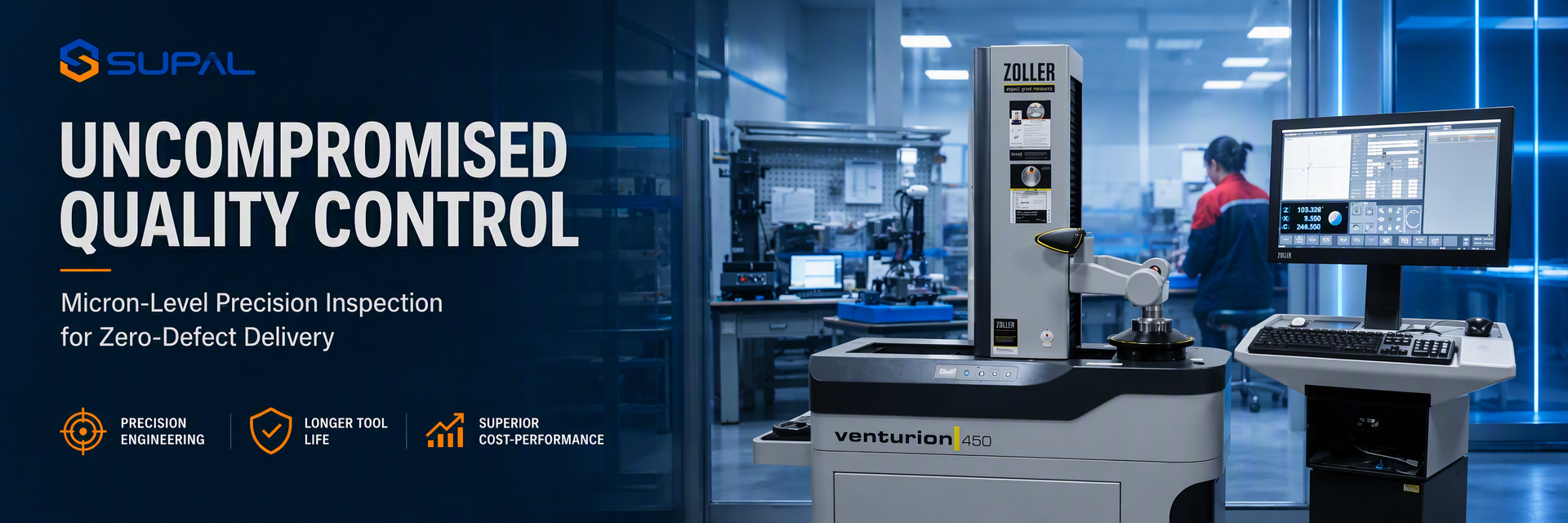
Trust Seal, Credit Check, RoSH and Supplier Capability Assessment. company has strictly quality control system and professional test lab.
China Supal (Changzhou) Precision Tools Co.,Ltd DEVELOPMENT
Internal professional design team and advanced machinery workshop. We can cooperate to develop the products you need.
China Supal (Changzhou) Precision Tools Co.,Ltd MANUFACTURING
Advanced automatic machines, strictly process control system. We can manufacture all the Electrical terminals beyond your demand.
China Supal (Changzhou) Precision Tools Co.,Ltd 100% SERVICE
Bulk and customized small packaging, FOB, CIF, DDU and DDP. Let us help you find the best solution for all your concerns.

Quality Carbide Milling Tools & Square End Mills manufacturer

Find Products That Better Meet Your Requirements.
Cases & News
The Latest Hot Spots.
Micro End Mill Vibration and Breakage: A Geometry and Parameter Control Guide
Micro End Mill Vibration and Breakage: A Geometry and Parameter Control Guide Micro end milling — typically involving tool diameters at the small end of the available range — occupies a different mechanical regime than standard-diameter milling. As tool diameter decreases, the tool's cross-sectional area shrinks far more sharply than its length in many applications, which means rigidity, runout sensitivity, and thermal behavior all become more critical, often before an operator notices any visible sign of trouble. A micro end mill can fail suddenly, sometimes with little or no visible wear beforehand, which makes prevention through geometry and parameter control far more effective than reactive troubleshooting after breakage. This guide helps CNC machinists, process engineers, and purchasing teams understand why small-diameter tools behave differently, how to select geometry suited to micro milling, and how to build a parameter strategy that reduces the risk of vibration and breakage rather than discovering the limits through trial and error. Why Small Diameter Changes the Mechanics of Milling Rigidity decreases disproportionately as diameter shrinks A tool's resistance to bending deflection is strongly related to its diameter. As diameter decreases, even a modest reduction can significantly reduce the tool's ability to resist radial forces. This means a micro end mill operating at what would be a routine engagement for a larger tool may already be near its practical limit. Runout has an outsized effect Radial runout that would be considered minor on a larger tool can represent a substantial percentage of a micro end mill's diameter. This uneven loading concentrates stress on one flute, accelerating wear or triggering sudden fracture well before the tool would otherwise be expected to fail. Heat concentrates quickly in a small mass A micro end mill has very little thermal mass compared to a standard tool. Heat generated at the cutting edge has less material to dissipate through, which can accelerate coating degradation or promote adhesion if cutting speed and cooling are not matched to the tool's scale. Chip evacuation becomes proportionally more difficult Flute volume shrinks along with diameter, so even a small amount of chip packing can represent a large percentage of available chip space. This makes micro milling more sensitive to material choice, chip form, and coolant or air delivery than equivalent operations at larger diameters. Failures can occur with little warning Because the tool's cross-section is small, the margin between stable cutting and structural failure is narrower. A micro end mill may show minimal visible wear right up until a sudden fracture, in contrast to the more gradual wear patterns typically seen on larger tools. Selecting Geometry for Micro Milling Stability Prioritize the shortest practical reach Tool projection has an amplified effect on deflection at small diameters. Use the shortest length of cut and shank projection that can complete the feature, and avoid selecting a longer tool "for flexibility" when a shorter one would suffice for the actual depth required. Match flute count to the operation and material A lower flute count generally provides more chip space relative to the tool's small cross-section, which can help in materials or operations prone to chip packing. In light-engagement finishing on very stable setups, a higher flute count may be considered, but chip evacuation must be verified rather than assumed. Supal's micro end mills can be compared across flute configurations for the specific application. Consider corner geometry carefully A sharp square corner concentrates stress at the most fragile point of an already delicate tool. Where the feature allows it, a corner-radius design can distribute load more evenly and reduce the likelihood of corner fracture. Supal's corner radius end mills provide a reference point for comparing corner strength options relevant to small-diameter and precision applications. Balance core diameter against chip space A thicker core improves rigidity and resistance to breakage but reduces flute volume for chip evacuation. This trade-off is more consequential in micro milling than in standard-diameter work, since both properties are already constrained by the small overall size. The correct balance depends on the specific material, engagement, and depth of cut. Consider custom geometry for demanding features When a standard micro end mill cannot satisfy the combination of reach, corner strength, and chip evacuation required by a specific feature, a custom milling tool may allow these parameters to be balanced specifically for that application rather than compromising with a generic design. Controlling Runout Before Adjusting Cutting Parameters Given how disproportionately runout affects small-diameter tools, verifying and minimizing runout should be one of the first steps in any micro milling setup, not a troubleshooting step reserved for after a failure. Clean the tool shank, collet, collet nut, and spindle taper thoroughly before every setup change. Inspect the collet for wear, contamination, or damage, since a worn collet is a common and often overlooked source of runout. Measure runout as close to the cutting edge as practical, using the shop's standard procedure. Confirm that the tool is seated fully and correctly in the holder before beginning the cut. If runout cannot be brought within an acceptable range for the tool diameter, address the holder and collet system before proceeding, rather than compensating through reduced cutting parameters alone. Building a Parameter Strategy That Reduces Breakage Risk Cutting speed, feed, and engagement for micro end mills should always begin from the tool supplier's published starting range for the exact diameter, flute count, coating, and material group. Because the margin for error is smaller at this scale, deviations from a validated starting point carry more risk than in standard-diameter milling. A cautious approach to establishing parameters Start from the supplier's exact-diameter recommendation. Micro end mill data is often diameter-specific rather than scalable from a larger tool in the same family; do not extrapolate from a different size. Confirm rigidity and runout before running the program. Address tool projection, holder condition, and runout as described above. Verify workholding and part stability at this scale. Small parts or thin features can move under even modest cutting forces, which is more likely to cause tool breakage at small diameters than at larger ones. Run an initial test cut at a conservative engagement. Observe sound, chip form, and any visible deflection before committing to full production parameters. Adjust one variable at a time. If chip packing, adhesion, or vibration appears, address that specific issue before changing multiple parameters together. Inspect the tool frequently during early production. Because failure can occur with limited warning, periodic inspection during initial runs helps confirm the process is stable before scaling to full batch production. Validate across a small batch before finalizing the process. A few successful parts do not guarantee long-term stability at this scale; monitor consistency before committing to unattended or high-volume production. If the tool breaks with little apparent warning Review runout, tool projection, and workholding rigidity first, since these factors have an outsized effect at small diameters. Confirm whether the failure occurred during a specific portion of the toolpath, such as an entry, corner, or interrupted region, since this can indicate an engagement spike rather than gradual wear. If vibration appears at engagement levels that would be stable for a larger tool Reduce tool projection and radial engagement first. A variable-helix geometry may help in some situations, but it cannot substitute for correcting excessive reach, poor workholding, or unacceptable runout. If chips are packing in the flutes Review flute count and chip space relative to the material's chip-forming behavior, and confirm that coolant, air, or lubrication is reaching the actual cutting zone rather than only the general tool area. Common Mistakes in Micro Milling Setup Reusing standard-diameter parameters scaled down proportionally Micro end mill behavior does not always scale linearly from larger tools. Use the supplier's data for the specific diameter rather than a simple proportional calculation. Treating runout as a troubleshooting step rather than a setup requirement At micro scale, runout that would be tolerable on a larger tool can be a primary cause of premature failure. Verify runout before running the program, not only after a problem occurs. Selecting the longest available tool for flexibility across multiple jobs A longer reach than necessary increases deflection risk disproportionately at small diameters. Match tool length to the actual feature depth required. Ignoring workholding stability for very small parts or features Small parts can move under forces that would be insignificant for larger components. Confirm that fixturing is adequate for the specific part size and geometry. Assuming a sharp square corner is always preferable for precision While a square corner may be required by the part geometry in some cases, where a radius is acceptable, it can meaningfully improve corner strength and reduce breakage risk at this scale. Frequently Asked Questions Why do micro end mills sometimes break without visible wear beforehand? Small cross-sections have a narrower margin between stable cutting and structural failure. Runout, excessive reach, workholding instability, or a sudden engagement change can cause fracture before a visible wear pattern develops, unlike the more gradual wear typical of larger tools. How much does runout actually matter at micro scale? Runout that represents a small percentage of a large tool's diameter can represent a much larger percentage of a micro end mill's diameter, concentrating load on one flute. Verifying and minimizing runout is one of the most effective preventive steps in micro milling. Should micro end mills always use a lower flute count? Not necessarily. A lower flute count often provides more chip space relative to the tool's size, which helps in operations prone to packing, but a higher flute count may be suitable for light-engagement finishing with proven chip evacuation. Match flute count to the specific operation and material. Can a corner radius really make a meaningful difference on such a small tool? Yes, proportionally more than on a larger tool, because the corner region is already a stress concentration and the tool's overall structure is more delicate. Where the part geometry allows a radius, it can improve resistance to corner fracture. What information should I provide when requesting a micro end mill recommendation? Provide the exact diameter, material grade, feature depth and geometry, required tolerance and surface finish, machine and holder details, measured runout if available, and any photographs of previous tool failures or breakage patterns. Conclusion Micro end mill vibration and breakage are best addressed through prevention rather than reaction, because failure at this scale can occur with limited visible warning. Controlling runout, minimizing tool projection, matching flute count and corner geometry to the operation, and building cutting parameters cautiously from the supplier's exact-diameter data are the most effective ways to reduce risk. Validate any process across a small batch before committing to full production, and inspect tools frequently during initial runs to confirm stability. Supal (Changzhou) Precision Tools Co., Ltd. supplies micro end mills and customized cutting solutions for precision machining applications. To evaluate a specific micro milling process, contact Supal with your exact tool diameter, material grade, feature geometry, machine and holder details, measured runout if available, and any photographs of previous tool breakage. This information helps identify a suitable tool geometry and a practical starting process for on-machine validation.

2026

08/20

How to Choose a Carbide End Mill for Hardened Steel (HRC 55-65)
How to Choose a Carbide End Mill for Hardened Steel (HRC 55-65) Machining hardened steel in the HRC 55 to 65 range is common in mold, die, and precision component manufacturing, but it places different demands on a carbide end mill than cutting the same steel in its annealed, pre-hardened state. As hardness increases, cutting forces rise, heat concentrates at the cutting edge, and the tool must resist abrasive wear and edge chipping simultaneously rather than favoring one property over the other. Selecting the right end mill for this hardness range is not simply a matter of choosing "the hardest coating available." Carbide grade, edge preparation, geometry, coating, tool rigidity, and a carefully built parameter strategy all interact. This guide helps CNC machinists, process engineers, and purchasing teams approach hardened-steel end mill selection systematically and build a controlled starting process for validation on the actual machine. Why HRC 55-65 Changes the Machining Problem Cutting forces and edge stress increase sharply As hardness rises through this range, the material resists deformation more strongly, which increases the force required to shear each chip. The cutting edge experiences higher stress per unit of engagement, making edge strength and support more critical than in softer material. Heat concentrates at a smaller contact zone Hardened steel tends to generate more localized heat at the cutting edge rather than distributing it broadly through the chip. Coating and substrate must manage this concentrated thermal load without softening or losing adhesion. Abrasive wear accelerates The hardened microstructure is more abrasive to the cutting edge, which can produce measurable flank wear more quickly than the same tool would experience in a softer material, particularly if cutting speed or coating selection is not matched to the hardness. Rigidity requirements become stricter Because cutting forces are higher, any deflection from excessive tool overhang, weak workholding, or an unsuitable toolpath is more likely to translate into vibration, chatter, or edge chipping than it would in an easier-to-cut material. Selecting Carbide Grade and Edge Preparation Fine-grain carbide substrates A fine-grain carbide substrate generally provides a favorable balance of hardness and toughness for hardened-steel applications, supporting both wear resistance and resistance to chipping under the higher cutting forces involved. The exact grade should be confirmed with the tool supplier for the specific hardness and operation. Edge preparation An edge that is too sharp may lack the support needed for hardened steel and can chip under load. A honed or slightly reinforced edge preparation is often used to add strength, though this must be balanced against cutting force: an overly blunt edge increases pressure and heat. The correct preparation depends on the specific hardness, tool diameter, and operation (roughing, semi-finishing, or finishing). Geometry Considerations for Hard Milling Flute count A higher flute count can support higher table feeds in light-engagement finishing operations on rigid setups, since each flute removes a smaller chip. However, in roughing or semi-finishing with greater engagement, chip space and core strength become more important, and a lower flute count with sufficient gullet volume may be more appropriate. The correct choice depends on the specific operation and depth of cut, not a single rule for all hardened-steel work. Corner design A sharp square corner concentrates stress precisely where hardened steel is most likely to cause chipping. A corner-radius geometry distributes load more evenly across the corner region and is often preferred for roughing and semi-finishing hardened steel, provided the part geometry allows a radius. Supal's roughing end mills can be compared for corner geometry and flute configuration suited to higher-engagement operations. Helix angle A moderate-to-high helix can help distribute cutting force more gradually across the engaged length of the flute, which may reduce shock loading on the edge compared to a low helix in an interrupted or high-load cut. The optimal angle depends on tool diameter, engagement, and the specific hardness being machined. Core strength and rigidity A thicker core supports the higher forces generated in hardened-steel machining but reduces flute volume. This trade-off should be evaluated against the operation: heavier engagement in roughing benefits from a stronger core, while light-engagement finishing can tolerate a design that favors edge sharpness. Coating Selection for Heat and Wear Resistance Hardened-steel applications commonly use coatings designed for high hot hardness and oxidation resistance at elevated cutting temperatures, such as AlTiN-, AlCrN-, or other multilayer PVD systems formulated for hard milling. The correct choice depends on the coating's specific composition, thickness, and adhesion characteristics rather than a marketing name alone, and should be confirmed with the tool and coating supplier for the target hardness range and cutting speed. A coating cannot compensate for an unsuitable substrate, edge preparation, or geometry. If the tool is chipping due to insufficient edge support or the wrong flute design, a different coating alone is unlikely to resolve the issue. Rigidity and Tool Reach in Hard Milling Because cutting forces are elevated in hardened steel, tool projection and workholding rigidity matter more than in softer materials. Minimize overhang wherever the feature allows, and confirm that the holder and collet are clean, properly seated, and free of runout. For deep cavities or detailed mold features that require extended reach, a long-neck design is often necessary, but the added flexibility of a longer neck interacts directly with the higher forces of hard milling. Supal's long neck end mills should be selected with attention to the shortest workable neck length and a core diameter matched to the expected engagement in the hardened material. When a standard geometry cannot satisfy the combination of reach, corner design, and edge support required for a specific hardened-steel feature, a custom milling tool can allow the neck length, core diameter, and edge preparation to be tailored to that application. Building a Parameter Strategy for Hardened Steel Cutting speed, feed, and engagement should always begin from the tool supplier's published range for the specific carbide grade, coating, tool diameter, and target hardness. Treat these as a starting reference, then validate on the actual machine, holder, and workpiece. Sequence for establishing a hard-milling process Confirm the exact hardness and material grade. HRC 55 and HRC 65 can behave differently even within the same base alloy; confirm the actual value rather than assuming a range. Match tool geometry to the operation. Roughing, semi-finishing, and finishing each favor different flute counts, corner designs, and edge preparations. Select carbide grade and coating for the hardness and cutting speed. Confirm with the supplier rather than reusing a mid-hardness selection. Set an initial engagement and speed. Use the supplier's range for the exact tool diameter and target hardness. Run a controlled test cut and inspect. Check for chipping, flank wear, surface finish, and spindle load trend. Adjust one variable at a time. Test changes to speed, feed, or engagement individually rather than together, and record the outcome. Confirm repeatability. A single successful pass does not guarantee a stable process; validate across a small batch before finalizing parameters for production. If the tool is chipping Review edge preparation, corner design, tool rigidity, and whether engagement is too aggressive for the operation. Confirm that the toolpath does not create sudden load spikes at corners or entry points. If wear is accelerating faster than expected Check whether cutting speed and coating are matched to the actual hardness, and confirm that coolant or air delivery, if used, is reaching the cutting edge consistently. If chatter appears Reduce unnecessary tool overhang, verify workholding rigidity, and confirm runout before adjusting cutting parameters further. Common Mistakes in Hardened-Steel Tool Selection Choosing a coating without confirming the substrate and geometry match the hardness A high-performance coating cannot compensate for an edge preparation or flute design that is not suited to the actual hardness and operation. Using a roughing geometry for a light-engagement finishing pass, or the reverse Each operation favors a different balance of flute count, edge sharpness, and rigidity. A mismatch can lead to either excessive tool wear or an unnecessarily conservative process. Applying the same parameters across the full HRC 55-65 range Hardness within this range can vary enough to require different speeds, feeds, or engagement levels. Confirm the actual measured hardness for the specific batch or component when possible. Ignoring tool reach when selecting a long-neck tool for a hardened die feature The combined effect of reduced rigidity and elevated cutting forces in hardened steel makes tool projection especially important. Use the shortest workable neck length for the feature. Reducing feed as the first response to chipping A large feed reduction can cause rubbing and additional heat, which may worsen rather than resolve chipping caused by an edge or geometry mismatch. Diagnose the root cause before making significant parameter changes. Frequently Asked Questions Is a higher flute count always better for hardened steel? Not necessarily. More flutes can support higher feeds in light-engagement finishing, but roughing and semi-finishing operations often benefit from a lower flute count with more chip space and a stronger core. Match flute count to the specific operation. Can the same end mill be used for HRC 55 and HRC 65 material? It may be possible depending on the tool's design and the tool supplier's stated range, but cutting parameters, expected tool life, and edge condition should be validated separately for each actual hardness rather than assumed to be identical. Should hardened steel be milled dry or with coolant? This depends on the coating, tool design, machine capability, and specific application. Follow the tool and coating supplier's guidance, since an inconsistent thermal condition — switching between wet and dry unpredictably — can be more damaging than a single, deliberate strategy. Why does the tool chip even though the coating is rated for hard milling? Coating alone cannot resolve chipping caused by insufficient edge support, excessive engagement, tool deflection from excessive overhang, or a corner geometry unsuited to the load. Review substrate, edge preparation, and rigidity alongside the coating. What information should I provide when requesting a hardened-steel end mill recommendation? Provide the exact hardness (HRC), material grade, operation type (roughing, semi-finishing, or finishing), feature geometry and depth, tool diameter and reach requirements, machine and holder details, and any current wear or chipping photographs. Conclusion Selecting a carbide end mill for hardened steel in the HRC 55-65 range requires balancing edge strength, wear resistance, geometry, and rigidity against the specific operation and measured hardness. A fine-grain substrate and suitable coating are necessary but not sufficient on their own; flute count, corner design, edge preparation, and tool reach must be matched to whether the operation is roughing, semi-finishing, or finishing. Build cutting parameters from the supplier's starting range, adjust one variable at a time, and validate across a small batch before committing to full production. Supal (Changzhou) Precision Tools Co., Ltd. supplies carbide end mills and customized cutting solutions for hardened-steel and mold-and-die applications. To evaluate a specific hardened-steel operation, contact Supal with your exact hardness, material grade, operation type, feature geometry, machine and holder details, and any current wear or chipping photographs. This information helps identify a suitable tool geometry and a practical starting process for on-machine validation.

2026

08/18

Thread End Mill Chipping and Chatter: A Diagnostic Guide for CNC Thread Milling
Thread End Mill Chipping and Chatter: A Diagnostic Guide for CNC Thread Milling Thread milling replaces a dedicated tap with a single tool that can cut multiple thread sizes and both internal and external threads using a helical toolpath. This flexibility comes with a different failure profile than tapping or single-point threading. Because a thread end mill cuts the full thread form through a circular, helical motion rather than a single axial pass, tooth-level chipping, chatter, and premature wear often trace back to the toolpath, helical interpolation parameters, and tool support rather than the carbide grade alone. This guide helps CNC machinists, process engineers, and purchasing teams distinguish tooth chipping from chatter, connect each pattern to its most likely cause, and build a controlled process for thread milling that avoids scrapped parts and inconsistent thread quality. Why Thread Milling Fails Differently Than Other Operations A thread end mill cuts the complete thread profile using a helical interpolation path: the tool moves in a circular motion around the bore or boss while simultaneously advancing axially by one thread pitch per revolution. Each tooth engages the material intermittently as it passes through the cut, similar to milling, but the tool must also maintain the precise geometric relationship that defines thread pitch and form. This combination means that problems can originate from several places at once: The programmed helical toolpath and its interpolation quality The tool's rigidity and support given its length and diameter relative to the thread depth The number of teeth engaged in the thread profile and how load is distributed among them The material's tendency to chip, tear, or work-harden at the thread crest and root Coolant delivery into a helical, often partially enclosed cutting zone A tool that performs well in one thread size or material may show different failure patterns in a deeper thread, a smaller diameter, or a tougher material, even when the nominal cutting data looks similar on paper. Distinguishing Chipping From Chatter Signs of tooth chipping Chipping in thread milling typically shows as damage to the crest, flank, or root of individual thread-forming teeth, rather than the smooth, even wear expected from normal use. Indicators include: Fragments visibly missing from one or more thread-forming teeth Inconsistent thread depth or form on different passes with the same program A rough or torn thread profile rather than a clean, defined form Premature loss of thread-forming capability well before an expected wear-based replacement point Debris or fine particles in the chip stream that do not match the expected chip shape for the operation Signs of chatter Chatter in thread milling is self-excited vibration between the tool, workpiece, and machine system. It often produces: Repeating wave patterns on the thread flank surface Audible tonal vibration during the helical pass rather than a steady cutting sound Inconsistent thread finish that changes at a regular interval around the circumference Increased sensitivity to spindle speed changes, with certain speeds producing noticeably worse results Chatter and chipping can coexist: sustained vibration can eventually chip a tooth, while pre-existing tooth damage can also promote irregular, chatter-like vibration on subsequent passes. Identifying which came first requires examining the earliest signs of degradation rather than only the final failure. Common Causes of Tooth Chipping Excessive radial engagement in a single pass Programming too much thread depth to be cut in one or two helical passes increases the load on each tooth. Thread milling often benefits from a defined number of passes that distributes the material removal more evenly, particularly in harder materials or deeper thread engagements. Insufficient tool support relative to thread depth A thread end mill operating near the limit of its usable length for a given diameter has less rigidity to resist the radial forces generated during helical interpolation. This can allow enough deflection to create uneven tooth loading, which appears as chipping concentrated on specific teeth rather than distributed evenly. Interrupted or work-hardened entry conditions Threading into a previously drilled or bored hole with an inconsistent surface, scale, or a work-hardened layer can subject the first engaging teeth to an unpredictable initial load. This is more likely to cause localized chipping at entry rather than uniform wear. Toolpath direction and lead-in/lead-out quality An abrupt lead-in or lead-out, rather than a smooth arc engagement and disengagement, can create an instantaneous load spike on the first or last tooth to contact the material. Verify that the CAM-generated helical path includes appropriate arc entry and exit rather than a direct radial engagement. Coolant not reaching the actual thread-forming zone If coolant is aimed generally at the tool rather than specifically supporting the helical cutting zone, heat and friction can build unevenly around the circumference, which may contribute to inconsistent tooth loading and premature chipping in certain materials. Common Causes of Chatter in Thread Milling Excessive tool overhang for the diameter and thread depth As with other milling operations, unnecessary tool projection reduces rigidity. In thread milling, this can be compounded by the helical motion, which introduces continuously changing force direction around the tool axis. Unstable workholding or thin-walled features A thread cut near a thin wall, a flexible fixture, or an insufficiently clamped part can vibrate under the combined radial and axial forces of helical interpolation, even when the tool itself is adequately rigid. Spindle speed at or near a resonant frequency for the system Certain spindle speeds can excite vibration in a specific tool-holder-machine combination. If chatter appears at one speed and improves noticeably at a nearby speed with no other change, resonance is a likely contributor. Incorrect number of passes for the thread depth and material Attempting to cut a full thread depth in too few passes increases both the radial engagement per pass and the likelihood of unstable cutting conditions, particularly in tougher or more abrasive materials. A Controlled Diagnostic Sequence When chipping or chatter appears in thread milling, work through the process systematically rather than changing several variables at once. Document the failure pattern. Note which teeth are affected, whether damage is concentrated at entry, mid-cut, or exit, and whether the surface shows chipping, tearing, or wave-like chatter marks. Verify the CAM-generated toolpath. Confirm arc lead-in and lead-out, the number of helical passes, and the radial engagement per pass against the tool supplier's recommendation for the material and thread size. Check tool projection and holder condition. Confirm the tool is not extended beyond what the thread depth requires, and that the holder and collet are clean and properly seated. Inspect workholding and part rigidity. Confirm the workpiece and fixture do not allow movement under the combined radial and axial loads of helical interpolation. Review entry conditions. Check whether the pre-machined hole or boss surface is consistent, and whether an interrupted or hardened layer is affecting the first engaging teeth. Confirm coolant delivery to the helical cutting zone, not just the general tool area. Adjust one variable at a time. Test changes to the number of passes, spindle speed, or feed individually, and record chip form, sound, and thread quality after each change. Validate over a small batch. A single successful thread does not confirm process stability; verify consistency across several parts before finalizing the program. Numerical starting parameters, including recommended radial engagement per pass and cutting speed, should always come from the tool supplier for the exact thread size, material, and coating. These values must be treated as a starting reference and validated on the actual machine, holder, and workpiece. Common Mistakes in Thread Milling Troubleshooting Blaming the carbide grade before checking the toolpath Many thread-milling failures originate in the CAM-generated helical path, the number of passes, or tool support rather than the tool material itself. Verify the programming and mechanical setup before changing tool grade or coating. Cutting the full thread depth in a single pass to save cycle time Reducing the number of passes increases load per tooth and raises the risk of chipping, particularly in harder materials or deeper thread engagements. Confirm the supplier's recommended pass strategy for the specific thread size and material. Ignoring where in the cut the damage begins Damage concentrated at entry points toward toolpath lead-in or workpiece surface condition, while damage distributed evenly around the thread may point toward vibration, tool support, or overall load levels. Treating all failures as the same problem can lead to the wrong fix. Changing spindle speed and feed simultaneously When troubleshooting chatter or chipping, changing multiple parameters together makes it difficult to identify which change resolved or worsened the issue. Adjust one factor, test, and record the result. Reusing a program from a different machine without validation Toolpath and parameters proven on one machine-holder combination may behave differently on another due to differences in rigidity, spindle characteristics, and holder runout. Validate before full production use. Frequently Asked Questions How can I tell if thread milling chatter is caused by the tool or the workholding? Compare the vibration pattern across different parts and setups. If chatter appears consistently regardless of fixture or part, tool projection, holder condition, or spindle speed are more likely causes. If it appears only with certain parts or fixtures, workholding rigidity is a more likely factor. Is it normal for the first and last teeth in a helical pass to wear faster? Some additional loading at entry and exit is expected due to the engagement transition, but excessive or chipped damage specifically at these points often indicates an abrupt lead-in or lead-out rather than a smooth arc engagement, and should be reviewed in the CAM program. How many passes should a thread milling operation use? This depends on the thread size, material, and tool supplier's recommendation. There is no single universal number; deeper threads and harder materials generally benefit from more passes to distribute the load, while shallow threads in easier materials may require fewer. Can a coating reduce chipping in thread milling? A suitable coating can help manage friction, heat, and adhesion, but it cannot compensate for an unsuitable toolpath, excessive engagement per pass, inadequate tool support, or unstable workholding. Address the mechanical and programming factors first. What information should I provide when reporting a thread milling failure to a tool supplier? Provide the thread size and standard, material grade and hardness, hole or boss preparation method, number of passes currently used, tool diameter and projection, holder type, spindle speed and feed, coolant method, and photographs of the damaged teeth and thread surface. Conclusion Chipping and chatter in thread milling usually originate from the helical toolpath, tool support, or workholding rather than the carbide material alone. A systematic review of the CAM-generated path, engagement per pass, tool projection, entry conditions, and coolant delivery typically resolves the majority of failures before any change to tool grade or coating is needed. Diagnose the failure location and pattern first, then adjust one variable at a time and validate across a small batch before committing to a final process. Supal (Changzhou) Precision Tools Co., Ltd. supplies thread end mills, taper end mills, and customized cutting solutions for CNC thread milling applications. To review a thread milling issue, contact Supal with your thread size and standard, material grade, current toolpath strategy, tool projection, and photographs of the affected teeth or thread surface. This information helps identify a suitable tool geometry and a practical starting process for on-machine validation.

2026

08/11